Lab 4: Shear and 4-point bending
ENGR 059 • Fall 2026 • Swarthmore Engineering
1 Shear Stress — Background and Theory
1.1 Shear Stress
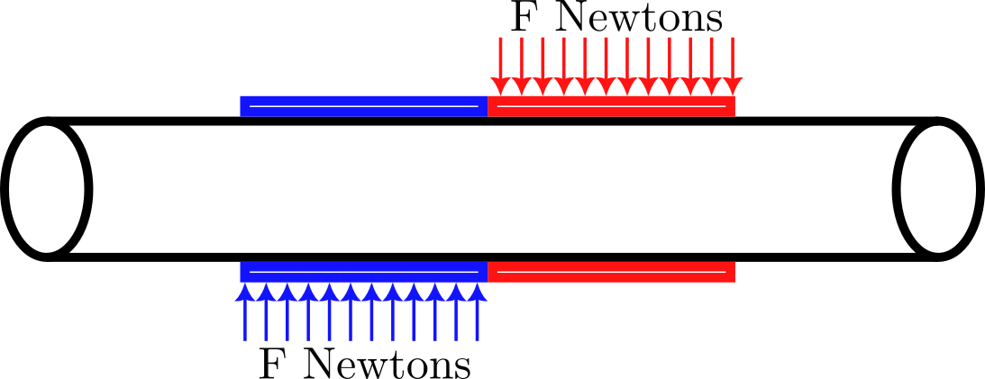
The average shear stress in a circular cross-section subjected to a transverse load is \[\tau_{\text{avg.}} = \frac{V}{A} = \frac{V}{\pi R^2},\] where \(V\) is the shear force and \(R\) the radius of the cross-section.
The shear stress anywhere in the cross-section is given by the formula \[\tau = \frac{V Q}{I t} \tag{1}\] where the meaning of each term is given from Hibbeler’s textbook (Figure 2).
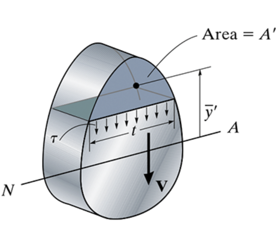
- \(V\) is the shear force
- \(I\) is the moment of inertia (or ‘second moment of the area’) of the cross-section
- \(t\) is the width, or thickness, of the cross-section experiencing shear, at the location where \(\tau\) is to be found, and
- \(Q = \bar{y}'A'\) is the first moment of the area, measured at the location where \(\tau\) is to be found. Here, \(A'\) is the area of the portion of the cross-section above where \(\tau\) is to be found, and \(\bar{y}'\) is the distance from the neutral axis to the centroid of \(A'\).
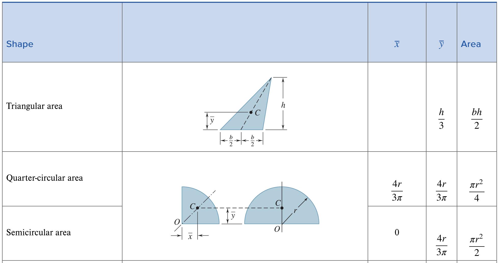
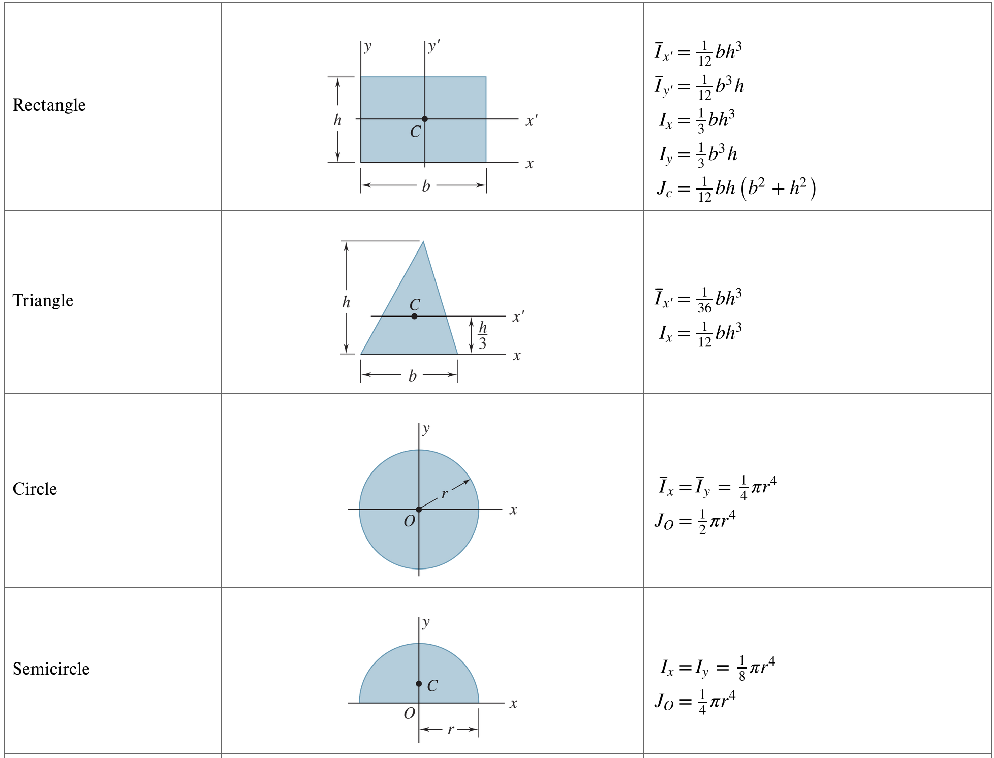
It may be helpful to consult Figure 3 and Figure 4 to help determine some of the quantities in the formula Equation 1.
1.2 First and second moments of area of common shapes
1.3 Average vs. Maximum Shear Stress
The maximum shear stress in any cross-sectional area occurs at the location where the ratio \(Q/t\) is a maximum.
The maximum shear stress in a circular cross-section subjected to a transverse load is related to the average shear stress in the same cross-section by the formula
\[\tau_{\text{max}} = \boxed{?} \tau_{\text{avg}}.\]
☞ Determine the value of \(\boxed{?}\).
1.4 Failure
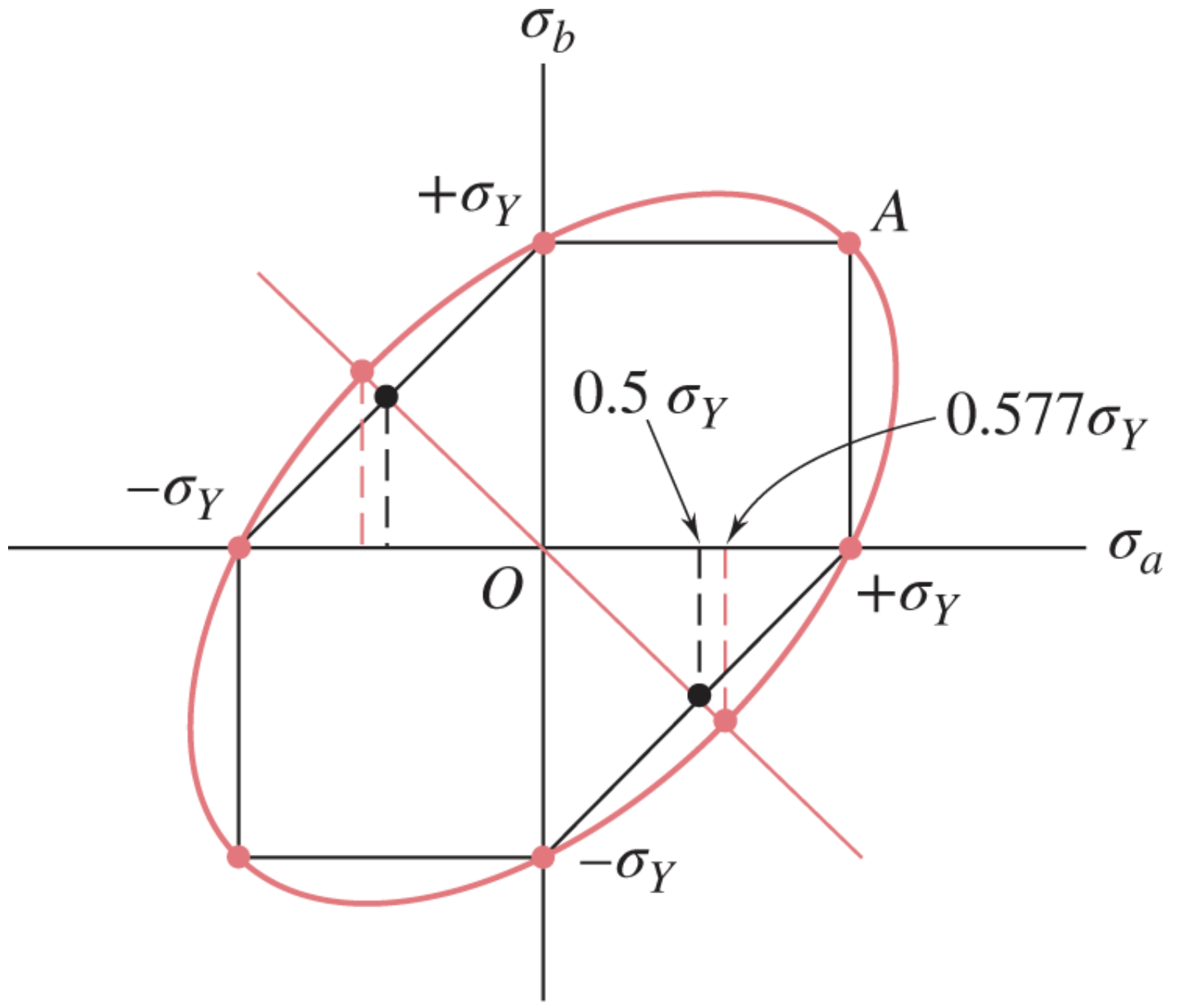
The tensile yield stress of a material reflects the stress at which the material would yield if it were subjected to a purely tensile load. In practice, materials often fail in shear, and the shear stress at which a material yields can often be different from the tensile yield stress. The ratio between the shear stress at which failure occurs and the normal stress at which failure occurs is given by two different theories to be the following:
- \(1/2\) according to the Tresca yield criterion
- \(1/\sqrt{3}\) according to the von Mises yield criterion
These two criteria can be visualized in Figure 5 in which the two principal stresses (assuming plane stress) are plotted against each other.
Estimate whether the samples in Table 1 will fail under the limitations of the PASCO Materials Testing System.
2 Four-Point Bending — Background and Theory
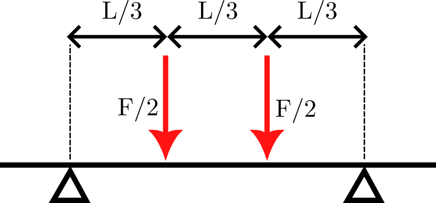
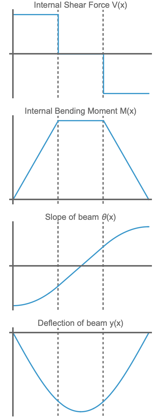
When a beam is subjected to 4-point bending as shown in the schematic in Figure 6, it experiences zero shear and non-zero bending moment in the mid-section. Figure 7 shows the shear, bending moment, slope, and deflection curves for a beam undergoing symmetric 4-point bending.
2.1 Normal Stress due to bending and shear stress due to shear
The maximum normal stress due to bending is given by the formula \[\sigma_{\text{max}} = \frac{M c}{I}, \tag{2}\] where \(M\) is the bending moment, \(c\) is the maximum distance from the neutral axis to an edge of the beam, and \(I\) is the second moment of the area of the cross-section about its neutral axis.
The beam experiences varying amounts of \(\sigma\) and \(\tau\) throughout its length and across its cross-section. We are concerned with the maximum values of these quantities anywhere in the beam. Use the material properties of Aluminum 6065 here.
☞ Use Equation 2 to predict the number of Newtons the load cell will read when the beam fails, if it fails due to normal bending stress.
☞ Use Equation 1 to predict the number of Newtons the load cell will read when the beam fails, if it fails due to shear stress.
2.2 Maximum and measured deflection
The maximum deflection experienced by a beam under 3-point bending occurs at the mid-point of the beam. However, in this experiment, we only have access to the deflection experienced by the prongs of the upper anvil, i.e., the position sensor of the PASCO Materials Testing Device measures the deflection at \(x/L = 1/3\) and \(x/L = 2/3\), not the maximum deflection.
The force applied by the load cell can be related to the deflection experienced at the loading anvils (and measured by the position sensor) using a spring constant \(k\) that is related to the stiffness of the beam using the following expression.
\[k = \frac{\text{Force}}{\text{Deflection}} = \boxed{?}\frac{EI}{L^3}.\]
☞ Determine the value of \(\boxed{?}\). It will be a relatively good-looking fraction.
3 Materials and Methods
3.1 Samples for shear
You are given 4 samples, with 2 specimens of each sample.
| Sample | Material | Diameter | Tensile Yield Strength (psi) |
|---|---|---|---|
| 1 | Aluminum | \(1/8\)” | 35,000 |
| 2 | Aluminum | \(1/16\)” | 35,000 |
| 3 | Steel | \(1/8\)” | 60,000 |
| 4 | Titanium | \(1/8\)” | 120,000 |
The samples are to be subjected to a pure shear load using ME-8239. A schematic for how ME-8239 loads the specimen is given in Figure 1, but note that this is only illustrative. For the purposes of calculation, you should assume that two point loads are applied in opposite directions.
3.2 Samples for 4-point bending
You will be provided two beams.
3.3 Attachments
Use the following attachments.
- ME-8237 Bending Accessory
- ME-8249 Four-point Load Anvil
- ME-8239 Shear Accessory
4 Procedure
Load all samples to failure if possible, adhering to the \(7,000\) Newtons limit on the load cell.
5 Report
Your report will consist of two distinct parts.
5.1 Shear
Write a report about the shear tests conducted in this lab. Use figures, tables, and equations as appropriate to illustrate your prediction of how these samples were expected to fail, and how failure actually occurred.
5.2 Four-point bending
Write a report about 4-point bending. Your report should address the following matters.
- Determine mathematical expressions for \(V\), \(M\), \(\theta\) and \(y\) as functions of \(x\). Leave your expressions in terms of \(F\), \(L\), \(E\) and \(I\) where appropriate.
- Derive the formula for the spring constant \(k\) and show how closely your measured force-deflection curves can be explained by this spring constant in the elastic region.
- Quantify the magnitude of normal stress and of shear stress is theoretically experienced by the beam during 4-point bending, and explain what kind of failure you predict the beam will undergo. Illustrate your calculations using graphs and equations.
- Report on the actual failure of the beam and comment on how well the theory worked.