Lecture 11
E21 Computer Engineering Fundamentals
Finite State Machines
- Finite State Machines (FSM) are an abstraction for computer hardware and software
- A FSM consists of:
- A set of states \(\mathcal{Q}\)
- A set of transitions \(\mathcal{T}: q \rightarrow r\), where \(q, r \in \mathcal{Q}\)
- The transitions are sometimes triggered by a set of inputs \(\mathcal{P}\)
- An execution of a FSM is a sequence of states \[q_0 \rightarrow q_1 \rightarrow q_2 \rightarrow \dots (\rightarrow q_n)\] that may or may not be finite.
A simple Finite State Machine
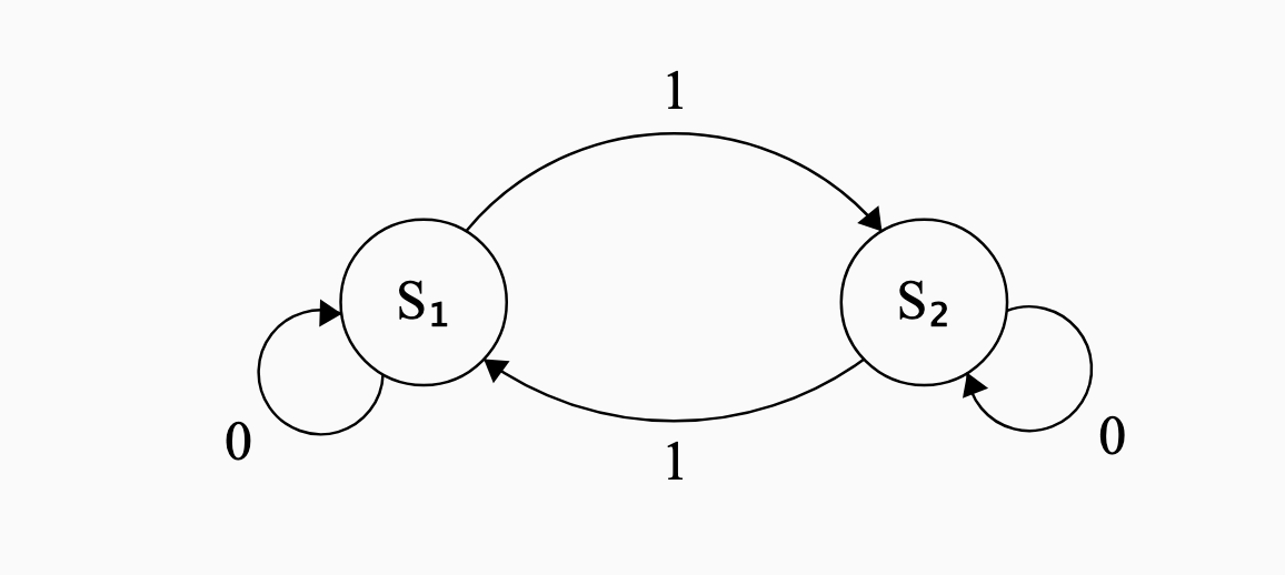
- Two states: \(S_1\) and \(S_2\)
- One binary input, \(1\) or \(0\)
- The transitions are shown in the following state-transition diagram
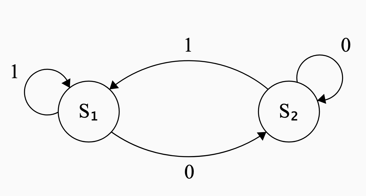
- The arrows are labeled with the inputs
- Circles are the states
Implementing a FSM on CPX
Modify the code so that it follows the state transition diagram Figure 1.
from adafruit_circuitplayground.express import cpx
import time

state = 1

while True:
    time.sleep(0.5)
    # Define what each state looks like
    if state == 1:
        cpx.pixels[5] = (0,0,50)
    elif state == 2:
        cpx.pixels[5] = (0,50,0)

    # Define transitions
    if state == 1 and cpx.button_a:
        state = 2
        continue

    if state == 2 and cpx.button_a:
        state = 1
        continue
Reading a State-Transition Diagram
- When state \(S_1\) receives input \(0\), the system goes into state \(S_2\)
- When state \(S_2\) receives input \(1\), the system goes into state \(S_1\)
- Giving input \(0\) to state \(S_2\) or input \(1\) to state \(S_1\) does not change the state
- but for completeness we make self-pointing arrows.
Interpreting a State-Transition Diagram
But what does this mean?
- A Finite State Machine is a ‘mental model’ for a real system
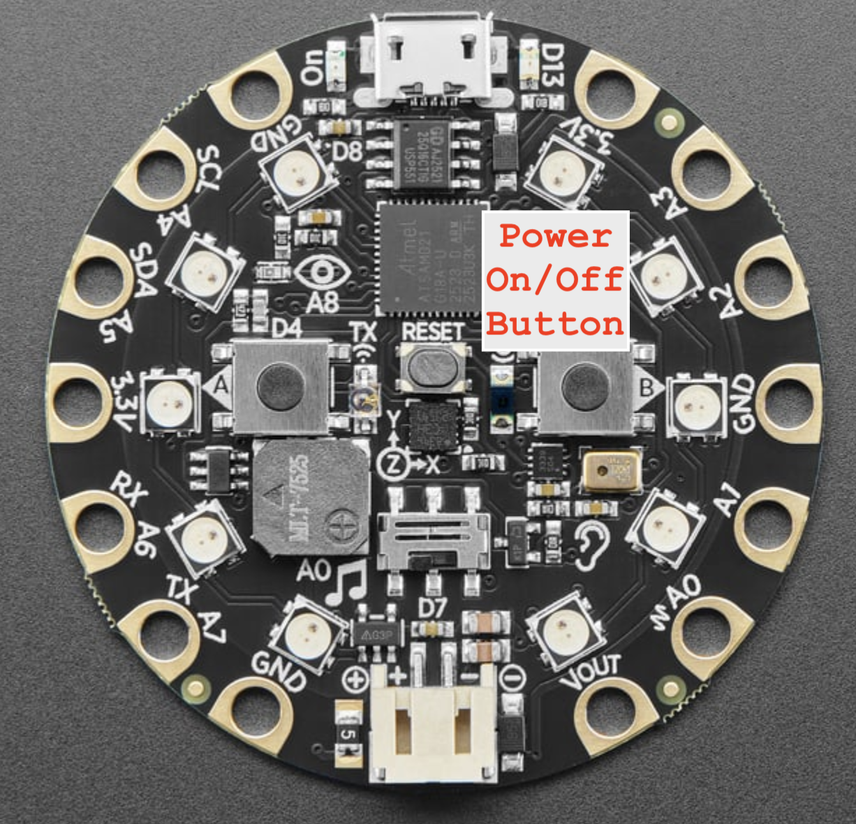
- A simple “power off/on button” for a light bulb.
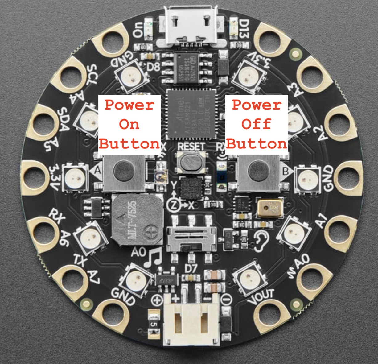
- States represent whether light is on/off
- Inputs: Button A, Button B
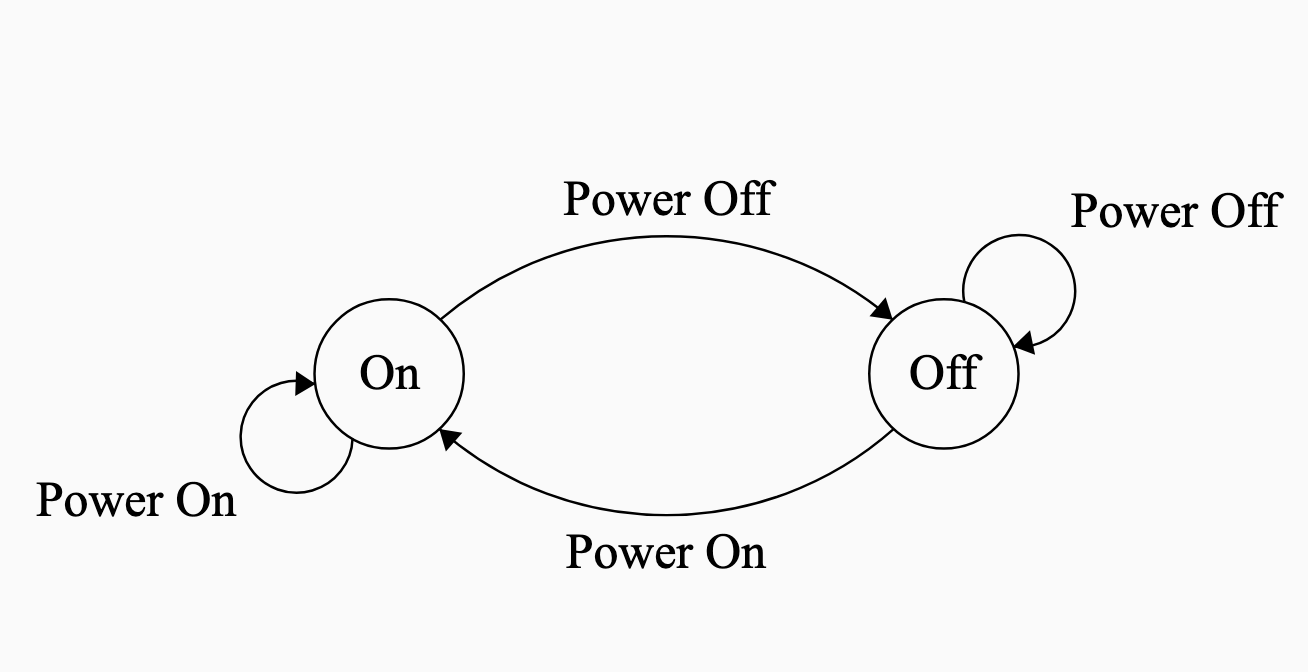
Another Finite State Machine
Interpret the following state-transition diagram. What kind of system could it represent?
Inputs:
1: Power Button Pressed0: Power Button not pressed
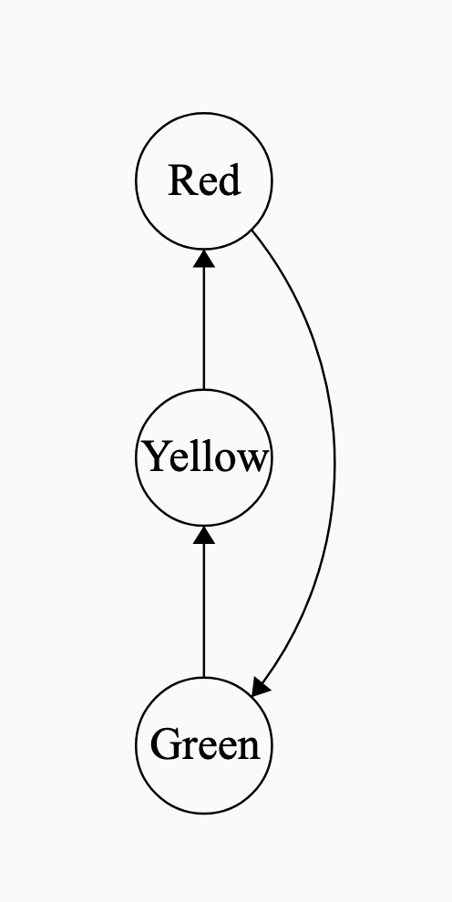
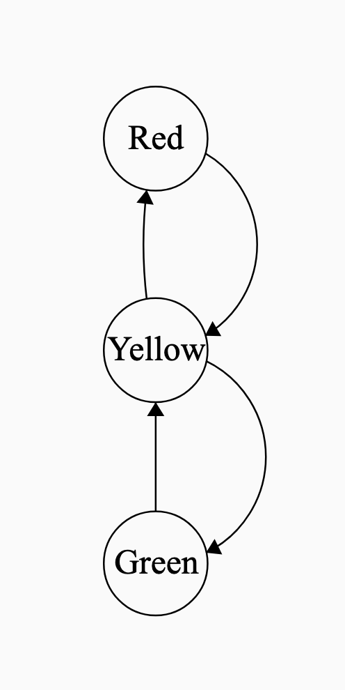
State Transition Diagrams with no input
Helpful even when there’s no input
Traffic lights
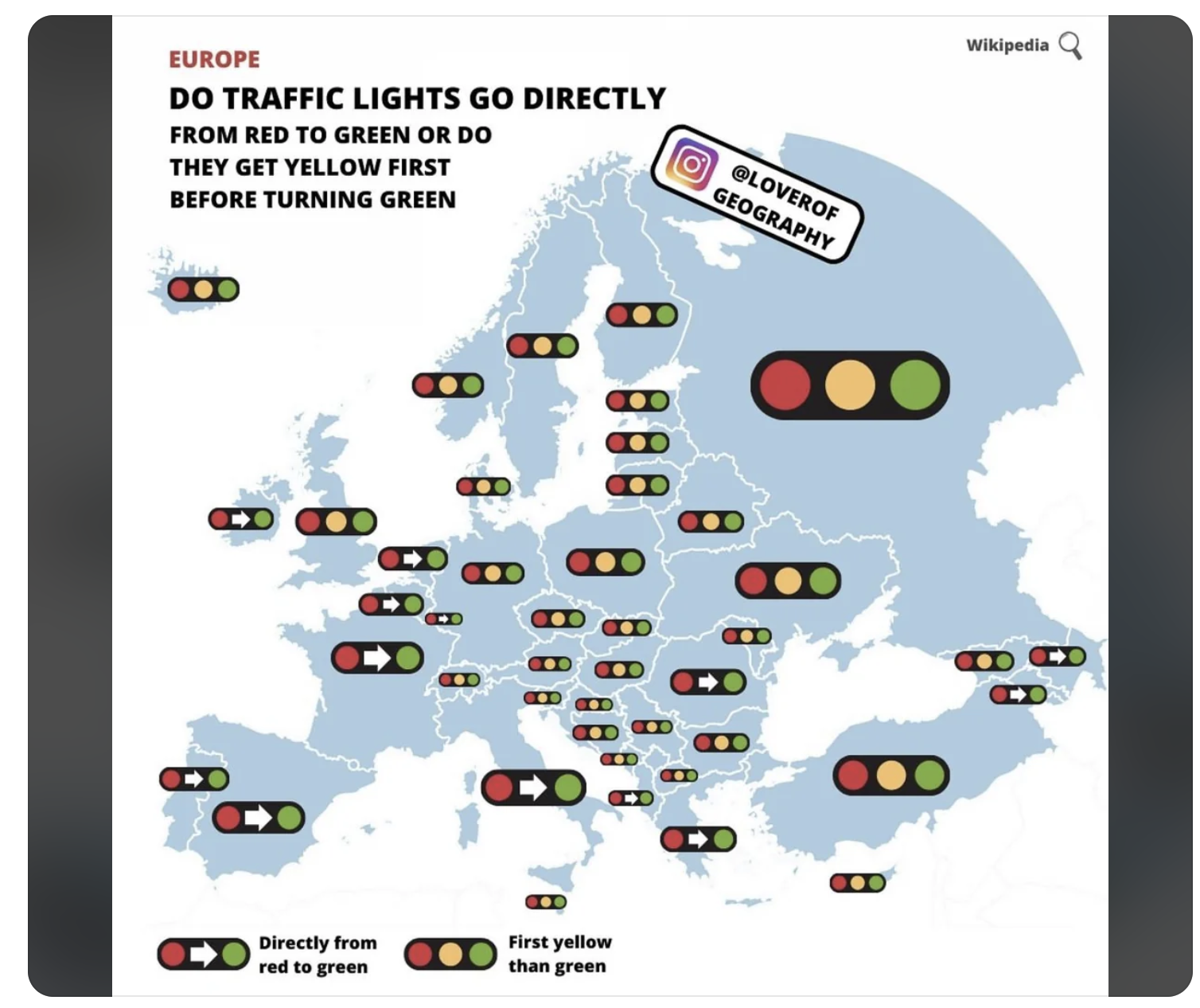
FSM for U.S. traffic lights and U.K. traffic lights
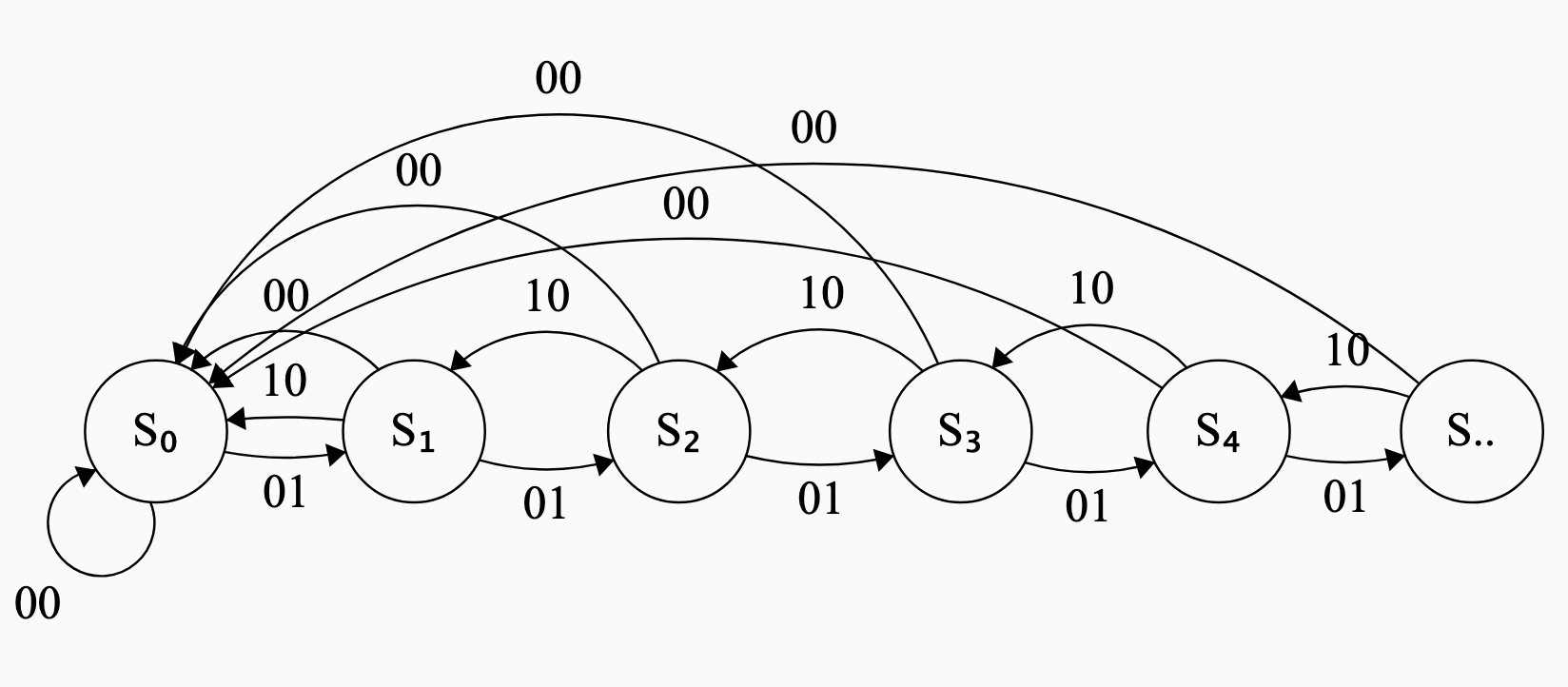
Finite State Machine for a counter
- Keeps count up to \(n\) steps.
- State \(S_1\) implies we have counted up to \(1\).
- State \(S_n\) implies we have counted up to \(n\).
- Three possible inputs to the system.
- Increment ( follow the
01arrows) - Decrement ( follow the
10arrows) - Reset (follow the
00)
- Increment ( follow the
Naming inputs and states using binary bits
It is customary to use binary bits to label each input
00: Reset01: Increment10: Decrement
If there are \(p\) inputs, need \(k\) bits to encode these inputs where \(2^k \ge p > 2^{k-1}\)
It is also customary to use binary bits to label each state
000: \(S_0\)001: \(S_1\)010: \(S_2\)011: \(S_3\)100: \(S_4\)101: \(S_5\)
Requirements for a Finite State Machine / State-Transition Diagram
For a State Transition Diagram to be complete:
- If there are \(m\) possible inputs, then there must be \(m\) outgoing arrows from each state, exactly one for each input.
- There is no corresponding restriction on the number of incoming arrows to each state.
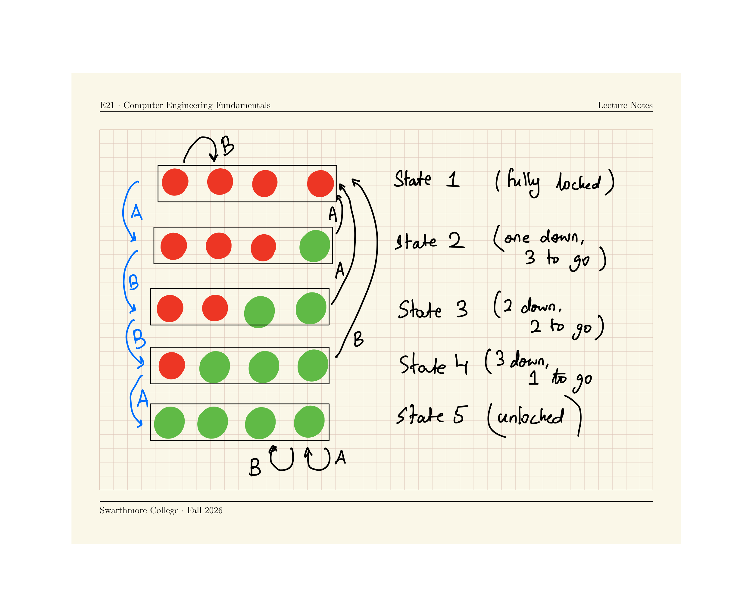
Combination Lock
Run the following code to implement a FSM for a 4-step combination lock on the Circuit Playground Express.
Press some combination of A and B to unlock your device. All four lights green = unlocked!
from adafruit_circuitplayground.express import cpx
import time

state = 1

def wait_till_release_A():
    while cpx.button_a:
        print("release button to complete transition")
        time.sleep(0.5)
def wait_till_release_B():
    while cpx.button_b:
        print("release button to complete transition")
        time.sleep(0.5)

while True:
    time.sleep(0.05)
    # Define what each state looks like
    if state == 1:
        # Locked state
        for k in range(0,4):
            cpx.pixels[k] = (50,0,0)
    elif state == 2:
        # One correct entry
        for k in range(1,4):
            cpx.pixels[k] = (50,0,0)
        cpx.pixels[0] = (0,50,0)
    elif state == 3:
        # Two correct entry
        for k in range(2,4):
            cpx.pixels[k] = (50,0,0)
        for k in range(0,2):
            cpx.pixels[k] = (0,50,0)
    elif state == 4:
        # Three correct entry
        cpx.pixels[3] = (50,0,0)
        for k in range(0,3):
            cpx.pixels[k] = (0,50,0)
    elif state == 5:
        # Four correct entry -- unlocked !
        for k in range(0,4):
            cpx.pixels[k] = (0,50,0)

    if state == 1:
        if cpx.button_a:
            state = 2
            print("Button A pressed! moving from state 1 to state 2")
            wait_till_release_A()
        elif cpx.button_b:
            state = 1
            print("Button B pressed! moving from state 1 to state 1")
            wait_till_release_B()

    if state == 2:
        if cpx.button_a:
            state = 1
            print("Button A pressed! moving from state 1 to state 2")
            wait_till_release_A()
        elif cpx.button_b:
            state = 3
            print("Button B pressed! moving from state 1 to state 1")
            wait_till_release_B()

    if state == 3:
        if cpx.button_a:
            state = 1
            print("Button A pressed! moving from state 1 to state 2")
            wait_till_release_A()
        elif cpx.button_b:
            state = 4
            print("Button B pressed! moving from state 1 to state 1")
            wait_till_release_B()

    if state == 4:
        if cpx.button_a:
            state = 5
            print("Button A pressed! moving from state 1 to state 2")
            wait_till_release_A()
        elif cpx.button_b:
            state = 1
            print("Button B pressed! moving from state 1 to state 1")
            wait_till_release_B()
Draw the state transition diagram for this
State Transition Diagram for lock
ABBA opens the lock.