Lecture 12
E21 Computer Engineering Fundamentals
Test 2 Discussion
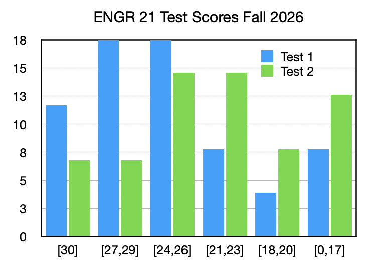
- Mean: 22.4
- Median: 23
Combination Lock — Review
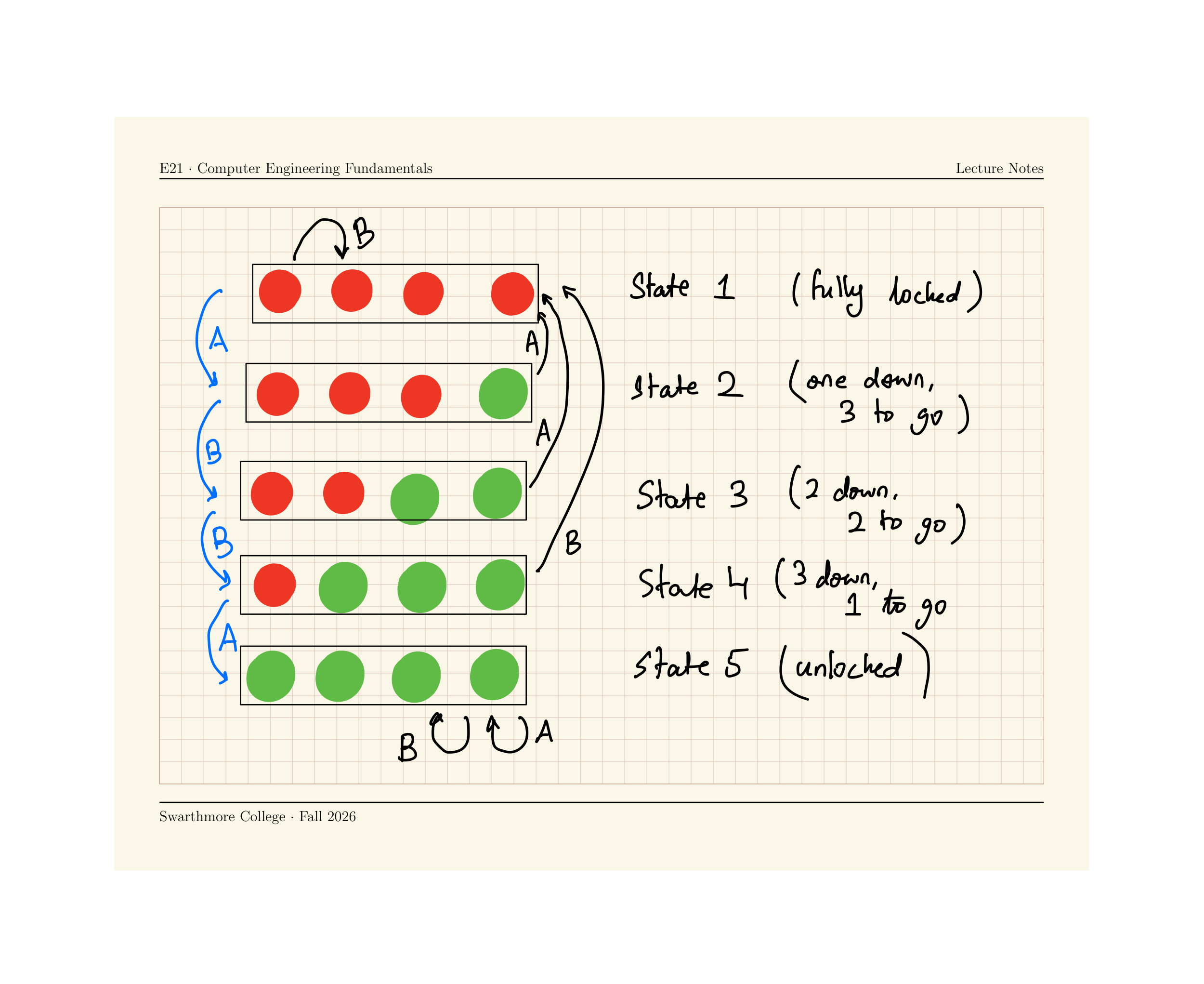
Run the following code to implement a FSM for a 4-step combination lock on the Circuit Playground Express.
Press some combination of A and B to unlock your device. All four lights green = unlocked!
from adafruit_circuitplayground.express import cpx
import time

state = 1

def wait_till_release_A():
    while cpx.button_a:
        print("release button to complete transition")
        time.sleep(0.5)
def wait_till_release_B():
    while cpx.button_b:
        print("release button to complete transition")
        time.sleep(0.5)

while True:
    time.sleep(0.05)
    # Define what each state looks like
    if state == 1:
        # Locked state
        for k in range(0,4):
            cpx.pixels[k] = (50,0,0)
    elif state == 2:
        # One correct entry
        for k in range(1,4):
            cpx.pixels[k] = (50,0,0)
        cpx.pixels[0] = (0,50,0)
    elif state == 3:
        # Two correct entry
        for k in range(2,4):
            cpx.pixels[k] = (50,0,0)
        for k in range(0,2):
            cpx.pixels[k] = (0,50,0)
    elif state == 4:
        # Three correct entry
        cpx.pixels[3] = (50,0,0)
        for k in range(0,3):
            cpx.pixels[k] = (0,50,0)
    elif state == 5:
        # Four correct entry -- unlocked !
        for k in range(0,4):
            cpx.pixels[k] = (0,50,0)

    if state == 1:
        if cpx.button_a:
            state = 2
            print("Button A pressed! moving from state 1 to state 2")
            wait_till_release_A()
        elif cpx.button_b:
            state = 1
            print("Button B pressed! moving from state 1 to state 1")
            wait_till_release_B()

    if state == 2:
        if cpx.button_a:
            state = 1
            print("Button A pressed! moving from state 1 to state 2")
            wait_till_release_A()
        elif cpx.button_b:
            state = 3
            print("Button B pressed! moving from state 1 to state 1")
            wait_till_release_B()

    if state == 3:
        if cpx.button_a:
            state = 1
            print("Button A pressed! moving from state 1 to state 2")
            wait_till_release_A()
        elif cpx.button_b:
            state = 4
            print("Button B pressed! moving from state 1 to state 1")
            wait_till_release_B()

    if state == 4:
        if cpx.button_a:
            state = 5
            print("Button A pressed! moving from state 1 to state 2")
            wait_till_release_A()
        elif cpx.button_b:
            state = 1
            print("Button B pressed! moving from state 1 to state 1")
            wait_till_release_B()
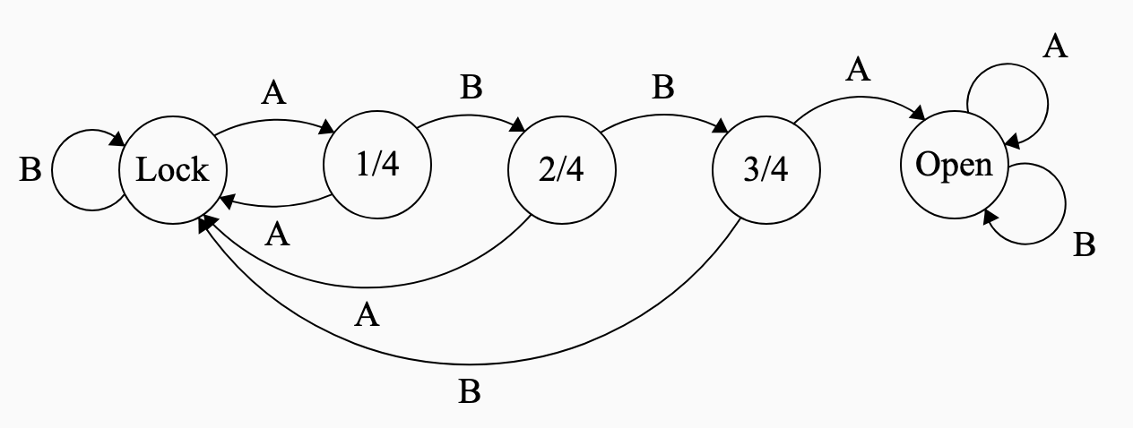
Draw the state transition diagram for this
State Transition Diagram for lock
ABBA opens the lock
State Transition Tables
| State | Input: A |
Input: B |
|---|---|---|
| Locked | 1 Correct | Locked |
| 1 Correct | Locked | 2 Correct |
| 2 Correct | Locked | 3 Correct |
| 3 Correct | Unlocked | Locked |
| Unlocked | Unlocked | Unlocked |
- State transition tables are an alternative to state transition diagrams for showing how a Finite State Machine works
- Each row corresponds to a possible current state of the system.
- Each column corresponds to a possible input to the system.
- Each entry corresponds to the new state that results.
Engineering Specifications to Finite State Machines
- The combination lock system is described by Table 1, Figure 1, Figure 3
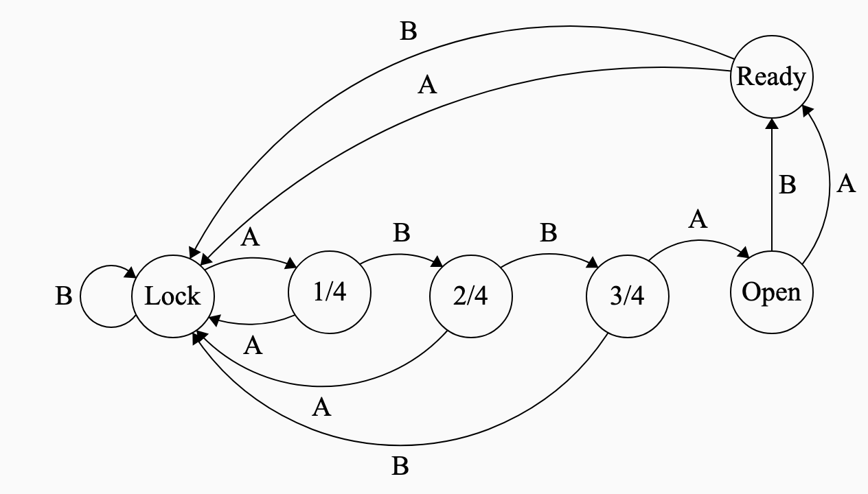
- Implement a new engineering specification:
- After unlock, any key should light all four LEDs blue.
- Any further key press should ‘lock’ it again.
- Add new entries to the state-transition table and modify the code to meet this specification.
Modified Lock FSM
To accommodate the new specifications:
Create a new state and add it to the table
State Input:
AInput:
BLocked 1 Correct Locked 1 Correct Locked 2 Correct 2 Correct Locked 3 Correct 3 Correct Unlocked Locked Unlocked Ready Ready Ready Locked Locked
Truth Tables for Finite State Machines
- A FSM can also be expressed as a truth table
- Need an encoding of the states and inputs using
0and1. - Let’s use a simply FSM with one binary state variable and one binary input: the retractable ball point pen.
- States: Nib out (
1), Nib retracted (0) - Input: Press button (
1), Don’t press button (0)
| State | Input | New State |
|---|---|---|
| 0 | 0 | 0 |
| 0 | 1 | 1 |
| 1 | 0 | 1 |
| 1 | 1 | 0 |
Logic Gates for Finite State Machines
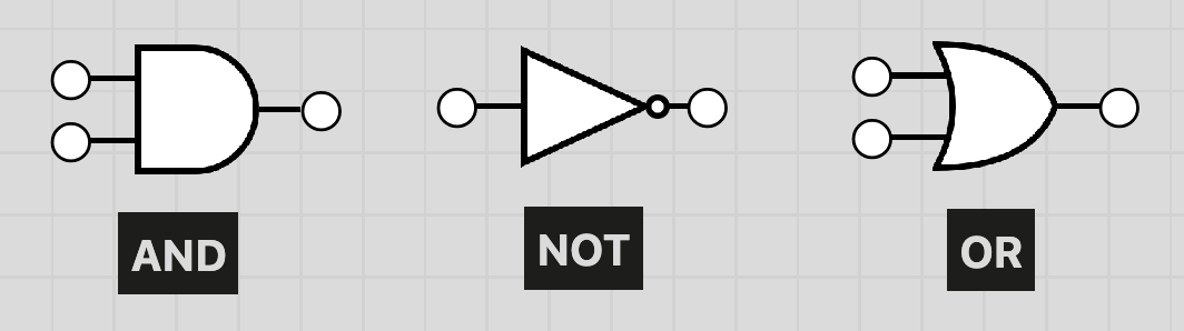
A AND B is True if and only if both A and B are True
NOT A is True if and only if A is False.
A OR B is True if and only if either A or B (or both) are True
These three logic gates can be used to implement truth tables, and therefore Finite State Machines
Implementing a Truth Table using Logic Gates
| State | Input | New State |
|---|---|---|
| 0 | 0 | 0 |
| 0 | 1 | 1 |
| 1 | 0 | 1 |
| 1 | 1 | 0 |
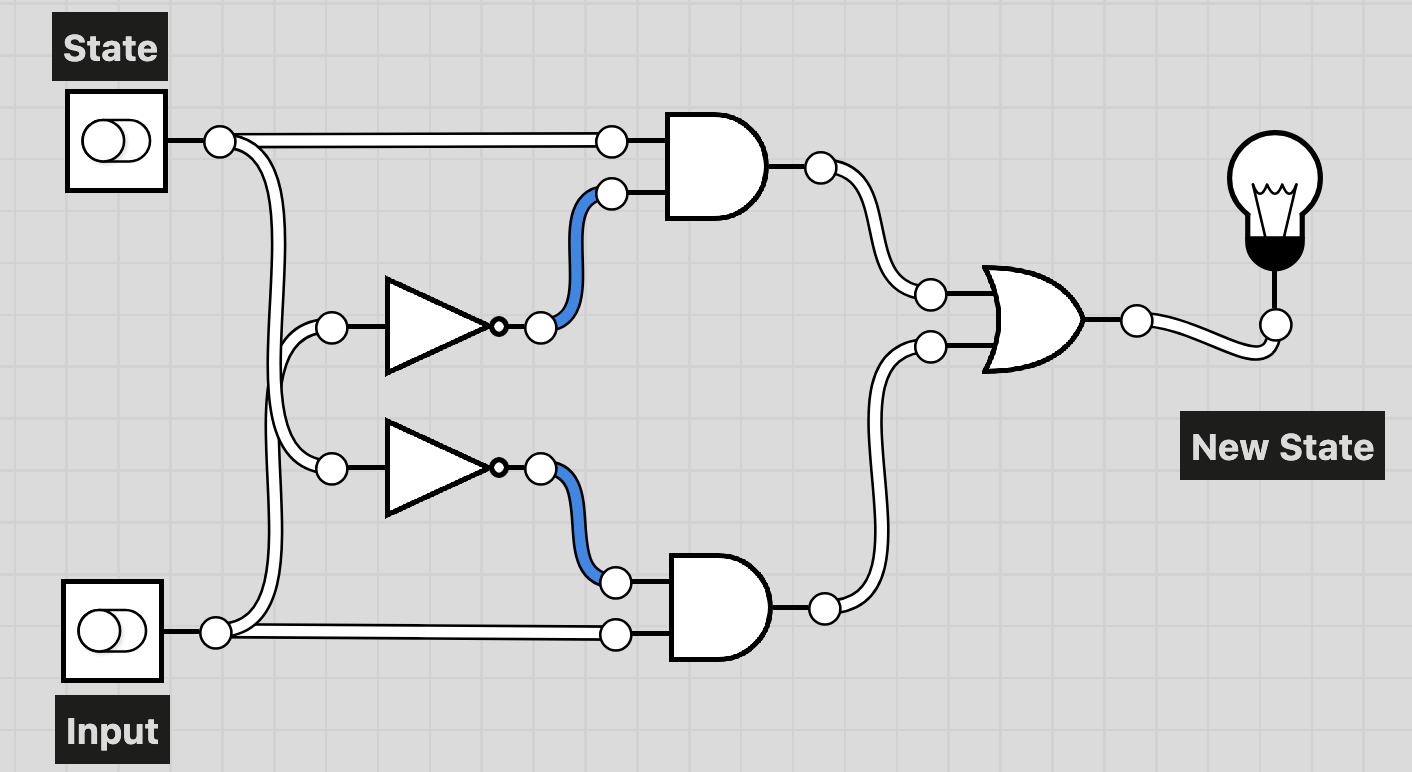
Truth Tables for systems with more than 4 state-input combinations
Let’s return to the 4-step combination lock.
| State | Input: A |
Input: B |
|---|---|---|
| Locked | 1 Correct | Locked |
| 1 Correct | Locked | 2 Correct |
| 2 Correct | Locked | 3 Correct |
| 3 Correct | Unlocked | Locked |
| Unlocked | Ready | Ready |
| Ready | Locked | Locked |
To get a truth table for this, we:
- Encode each state as a binary number. Locked:
000. 1 Correct:001. 2 Correct:010. 3 Correct:011. Unlocked:100. Ready:101. - Encode each input as a binary number: A =
0and B =1 - The choice of encoding is arbitrary, but will determine what the truth table looks like.
Truth Table for combination lock ABBA
| State | Input | New State |
|---|---|---|
000 |
0 |
001 |
000 |
1 |
000 |
001 |
0 |
000 |
001 |
1 |
010 |
010 |
0 |
? |
010 |
1 |
? |
011 |
0 |
? |
011 |
1 |
? |
100 |
0 |
101 |
100 |
1 |
101 |
101 |
0 |
000 |
101 |
1 |
000 |
| State | Input A 0 |
Input A 1 |
|---|---|---|
| ◯ ◯ ◯ ◯ | ✓ ◯ ◯ ◯ | ◯ ◯ ◯ ◯ |
| ✓ ◯ ◯ ◯ | ◯ ◯ ◯ ◯ | ✓ ✓ ◯ ◯ |
| ✓ ✓ ◯ ◯ | ◯ ◯ ◯ ◯ | ✓ ✓ ✓ ◯ |
| ✓ ✓ ✓ ◯ | ✓ ✓ ✓ ✓ | ◯ ◯ ◯ ◯ |
| ✓ ✓ ✓ ✓ | Ready | Ready |
| Ready | ◯ ◯ ◯ ◯ | ◯ ◯ ◯ ◯ |
Definitions:
| State | Encoding | Meaning |
|---|---|---|
| ◯ ◯ ◯ ◯ | 000 |
Locked |
| ✓ ◯ ◯ ◯ | 001 |
1 down |
| ✓ ✓ ◯ ◯ | 010 |
2 down |
| ✓ ✓ ✓ ◯ | 011 |
3 down |
| ✓ ✓ ✓ ✓ | 100 |
Unlocked |
| Ready | 101 |
Ready |
Fill in the new state column
A simple Finite State Machine: Building its State Transition Table
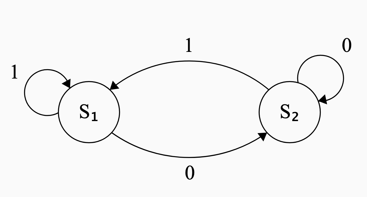
- Let’s build the state-transition table for this FSM.
- Naming convention: \(S_1\) is
0, \(S_2\) is1.
| State | Input 0 |
Input 1 |
|---|---|---|
0 |
1 |
0 |
1 |
1 |
0 |
A simple Finite State Machine: Building its Truth Table
- Let’s build the truth table for this FSM.
- Naming convention: \(S_1\) is
0, \(S_2\) is1.
| State | Input | New State |
|---|---|---|
0 |
0 |
1 |
0 |
1 |
0 |
1 |
0 |
1 |
1 |
1 |
0 |
A simple Finite State Machine: Implementing it with Logic Gates
| State (A) | Input (B) | New State |
|---|---|---|
0 |
0 |
1 |
0 |
1 |
0 |
1 |
0 |
1 |
1 |
1 |
0 |
Draw a logic-gate diagram for this truth table using AND OR and NOT
Strategy:
Look for a combination of and, or and not statements that describe the new state column in terms of the other two columns.
Write out a boolean statement in words.
New State is
1if State and Input are both0, or if State is1and Input is0.Write down the conditions needed for New State to be
1.=
(not A and not B) or (A and not B).Otherwise, New State is assumed to be
0because of the law of excluded middle
Summary
We have learned four different ways of representing a Finite State Machine:
- State transition diagram
- State transition table
- Truth table
- Logic gates diagram